In my research project, at one stage I needed an orient constraint that works locally, i.e. it works only on the hierarchy below a particular transform. I believe we could do that by re-connecting orient constraint's targetMatrix. However, since I don't know how orient constraint works under the hood and it does not allow me to have dynamic offset, I had to come up with my own constraint using matrix calculations.
So I have been digging into how transforms work and how to visualize the matrix concatenation. I was successful at making such constraint. However, I am still working on adding an offset that can dynamically be changed without affecting the rotation of the controlled object. I have yet to use this on my research project (fingers crossed). But, knowing I had success with a sample hierarchy gives me hope.
Follow this thread for detailed discussion on this orient constraint. LINK
edit: (26.06.09)
Later in my research I realized that what I had found out was not the best solution for what I was doing.

26 May, 2009


Continue on Twist
The best way to understand twist is to think of the joint as a vector and twist is a spin around that vector. This leads to the topic of how quaternion transform works. More on that later.
When it comes to vector related implementation two tools mentioned below are a great help.
-> Single IK chain with pole vector can act as a vector. And spin is defined by pole vector or twist attribute.
-> Aim constraint comes very handy when vectors are involved. You can use aim vector and up vector to control the rotation of an object.
Keep in mind though that they do flip at one point or the other. The pose does not change generally, but if you are doing calculations based on their rotation then you are highly prone to flipping issues.
When it comes to vector related implementation two tools mentioned below are a great help.
-> Single IK chain with pole vector can act as a vector. And spin is defined by pole vector or twist attribute.
-> Aim constraint comes very handy when vectors are involved. You can use aim vector and up vector to control the rotation of an object.
Keep in mind though that they do flip at one point or the other. The pose does not change generally, but if you are doing calculations based on their rotation then you are highly prone to flipping issues.
09 May, 2009
Twist Setup Notes
When doing a twist setup to distribute the rotation uniformly there are some important things to consider. Following are some notes from my experience while working on forearm and shoulder twist setups.
-> Twist cannot be associated with any single axis. Due to the nature of Euler angle, based on your rotation order axis that twist the joint could change.
For example,
A shoulder joint with zxy rotation order in rest position will twist around x-axis. But if you bring shoulders in front by rotating on y axis, now the z-axis is responsible for twist.
Hence, we cannot plug one axis from shoulder joint to the twist joints. Of course we can plug all three axis and it may work, but that's really not the elegant solution. Inspired by this tutorial, I think Aim constraint is the most elegant solution so far.

->Another issue is the source of twist and in which direction its propagating. For example, for forearm twist, rotation originates from the wrist joint and propagates towards the elbow joint. So the direction is from a child joint to its parent joint. However, in shoulder twist the direction is opposite, twist propagates from parent to the child joint. This changes the equation of how to make twist joints inherit motion from shoulder joint and dampen the rotation at the same time.
-> Twist cannot be associated with any single axis. Due to the nature of Euler angle, based on your rotation order axis that twist the joint could change.
For example,
A shoulder joint with zxy rotation order in rest position will twist around x-axis. But if you bring shoulders in front by rotating on y axis, now the z-axis is responsible for twist.
Hence, we cannot plug one axis from shoulder joint to the twist joints. Of course we can plug all three axis and it may work, but that's really not the elegant solution. Inspired by this tutorial, I think Aim constraint is the most elegant solution so far.

->Another issue is the source of twist and in which direction its propagating. For example, for forearm twist, rotation originates from the wrist joint and propagates towards the elbow joint. So the direction is from a child joint to its parent joint. However, in shoulder twist the direction is opposite, twist propagates from parent to the child joint. This changes the equation of how to make twist joints inherit motion from shoulder joint and dampen the rotation at the same time.
06 May, 2009
Scale Constraint on Joints
It does not work properly. As I had posted earlier, joints use a special scale connection with inverseScale attribute (only joints have this tranform property) when you create a chain hierarchy. This gives a special behavior when scaling a parent joint. And using scale constraint messes up this inverseScale calculation in joint transform and so the child joints scale weirdly when scaling the parent joint.
So use connection and a blend node(blendColors) on a joint chain to blend between scale values.
edit:
From reading on forums I get that the problem is with constraints not taking "segment scale compensation" into consideration. So orient constraint suffers from the same problem. I had encountered this problem when working on a stretchy setup on arms.
So use connection and a blend node(blendColors) on a joint chain to blend between scale values.
edit:
From reading on forums I get that the problem is with constraints not taking "segment scale compensation" into consideration. So orient constraint suffers from the same problem. I had encountered this problem when working on a stretchy setup on arms.
29 April, 2009
BlendShapes 1
If somehow (or by doing something stupid like I did) if you have blendshapes created which don't have the same vertex order as your base geometry or if geometry changes in the base model, don't panic! You can use already created blendshapes to make new ones. Use a wrap deformer to do this as explained below.
-> Take all old blendshape geometry and add them to old base geometry using "Blend Shape" deformer.
-> Align new geometry poition to match with the old base geometry (which has blendshapes).
-> Apply a wrap deformer so the old base geometry drives the new base geometry.
-> Now dial in each blendshape individually (you just need to do it for one side, left or right). This will deform the new geometry as the old base geometry deforms.
-> Duplicate your new deformed geometry. You have got a blendshape for new geometry!
You can adjust the options in wrap deformer to get the best results. And when you dial blendshapes make sure you don't get any undesired deformations. You can actually paint blendshape weight to remvoe it later if you have any extra vertices being affected.
-> Take all old blendshape geometry and add them to old base geometry using "Blend Shape" deformer.
-> Align new geometry poition to match with the old base geometry (which has blendshapes).
-> Apply a wrap deformer so the old base geometry drives the new base geometry.
-> Now dial in each blendshape individually (you just need to do it for one side, left or right). This will deform the new geometry as the old base geometry deforms.
-> Duplicate your new deformed geometry. You have got a blendshape for new geometry!
You can adjust the options in wrap deformer to get the best results. And when you dial blendshapes make sure you don't get any undesired deformations. You can actually paint blendshape weight to remvoe it later if you have any extra vertices being affected.
20 April, 2009
Direction connection for rotation
From my experience so far, connecting rotation values directly is not a good practice. There are some pre-conditions that have to match in order for this to work. So you end up loosing quite a bit of flexibility and you have to make 110% sure that those conditions would not change after you make connections. Here are some main conditions that I learned.
1. Rotation orders have to be the exact same.
2. If local rotation axis between parent and child (relationship considering how connections are made) do not align all the time this will not work properly. So rotating parent will rotate child differently.
So if you still need to use the connections and solve at least the 2nd problem, then you need to create a node network that will find the offset between local rotation axis of both objects and then assign rotation value to the child object accordingly.
1. Rotation orders have to be the exact same.
2. If local rotation axis between parent and child (relationship considering how connections are made) do not align all the time this will not work properly. So rotating parent will rotate child differently.
So if you still need to use the connections and solve at least the 2nd problem, then you need to create a node network that will find the offset between local rotation axis of both objects and then assign rotation value to the child object accordingly.
19 April, 2009
FK controllers - not as simple as I had thought
FK controllers are trickier than they seem to be. They are not simple! Here are some questions and thoughts I encountered while doing an arm setup.
1. How to bind controllers to the joints: Parent shapes? Constraint? Connections? Or combination of all these?
2. Constraint works, but you cannot take advantage of joint's inveseScale attribute directly. Connections have more issues, and it starts getting complicated when you parent stuff. Because the values don't update in channel if you have connected transform values directly using translate and rotate. More complicated connections can be established using worldMatrix and parentInverseMatrix to get proper world space transform value, but it just ends up being more complicated than it has to be. Unless I have a simple node that does this, which is what parentConstraint is.
3. Now this leaves us to parent shape method. It seems that this technique works the best amongst other techniques. The main advantage is that when scaling all child controllers follow with their respective joints. Here are the problems with parent shape method.
1. How to bind controllers to the joints: Parent shapes? Constraint? Connections? Or combination of all these?
2. Constraint works, but you cannot take advantage of joint's inveseScale attribute directly. Connections have more issues, and it starts getting complicated when you parent stuff. Because the values don't update in channel if you have connected transform values directly using translate and rotate. More complicated connections can be established using worldMatrix and parentInverseMatrix to get proper world space transform value, but it just ends up being more complicated than it has to be. Unless I have a simple node that does this, which is what parentConstraint is.
3. Now this leaves us to parent shape method. It seems that this technique works the best amongst other techniques. The main advantage is that when scaling all child controllers follow with their respective joints. Here are the problems with parent shape method.
- You cannot use translation values because joints will have some values already in there.
- If you change rotation order of the controller you are changing the rotation order of the joint itself. This can cause the problem if you are blending between joint chains and you have not used constraints.
- The main problem is that by parenting a shape you are directly manipulating the joint, which I think is not a good idea.
- Scaling joints will also scale shapes (This could be good or bad).
18 April, 2009
True on the fly Rotation Order Change
True on the fly rotation order change means that the object should not jump from its current pose. I started looking into matrix to achieve this. Basically, I thought if I can formulate the equation that involves rotation values and rotation order I can solve that equation to get the rotation values that will keep the object in the same pose. I found that I could actually have separate matrices for each axis, RX, RY and RZ and then multiply them one by one based on rotation order to get this rotation value. However, in trying to find if I can set matrix value of an object using MEL I ended up finding a solution of my actual problem. It can't get simpler than this.
Select your object, rotate in any position and then change rotation order using this command. Object will stay in the same pose! Thanks to "-preserve" flag.
xform -preserve true -rotateOrder yxz;
Select your object, rotate in any position and then change rotation order using this command. Object will stay in the same pose! Thanks to "-preserve" flag.
17 April, 2009
"Easy Select" or "Proxy Select"
In the latest rigging project I have been working on this idea to make selection of controllers quick and easy. Generally the problem with curve controllers is that you cannot select them quickly because you have to be accurate in clicking the thin curves (unless you are an avid shooting game player and you have very high accuracy). In my experience sometimes it becomes a little annoying when it takes 3 clicks to select a controller.
So in this idea of "Easy Select" or "Proxy Select", I have hidden geometry that defines the selection area around a curve. Each controller has its own selection area defined this way. So instead of pin pointing on the curve you can click anywhere in this 3D area to select the curve controller. And a controller can have more than one objects defining its area, clicking on either of them will transfer selection to that controller.
I created a script to do this, so I click selection area geometry first and then select the target controller and click shelf button and I have "Easy Select" working for that controller. I also have an attribute on target controller so that I can turn this on and off. The big problem with this technique was that undo was creating this cycle where if I undo it goes back selecting proxy geometry and my scrip transfers that selection back to the control. And if I do undo again the same thing repeats. Hence I can't do any undo before "Easy Select" event. For the solution, I had to disable undo before I execute the function and turn it on at the end.
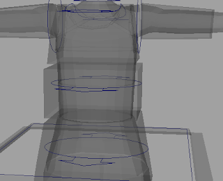 Different geo. that defines selection area for controllers.
So in this idea of "Easy Select" or "Proxy Select", I have hidden geometry that defines the selection area around a curve. Each controller has its own selection area defined this way. So instead of pin pointing on the curve you can click anywhere in this 3D area to select the curve controller. And a controller can have more than one objects defining its area, clicking on either of them will transfer selection to that controller.
I created a script to do this, so I click selection area geometry first and then select the target controller and click shelf button and I have "Easy Select" working for that controller. I also have an attribute on target controller so that I can turn this on and off. The big problem with this technique was that undo was creating this cycle where if I undo it goes back selecting proxy geometry and my scrip transfers that selection back to the control. And if I do undo again the same thing repeats. Hence I can't do any undo before "Easy Select" event. For the solution, I had to disable undo before I execute the function and turn it on at the end.
 Different geo. that defines selection area for controllers.
I am still working on this script to make UI to list all "Easy Select" objects and their selection area objects. Also, I need to add a function to delete the nodes & attributes that I am creating so if you want to delete this feature from the scene you don't have to do it manually.
Connecting Geo Display Type
Generally you can link geometry display type by adding them to a layer and switch between "template", "reference" or "normal". Alternatively you can change its display override type to reference directly in the attribute editor. In later case it become difficult to debug, if you have to go back and find that geometry and change display type to "normal".
I find it more organized if I have an attribute in the main controller (hidden from animators) that I can use to change the display type of all geometry. This way I can go back and select geometry easily by dialing the number for respective display type. Also if we expose less non-animation related things to animators its safer for the rig and cleaner for animators.

I find it more organized if I have an attribute in the main controller (hidden from animators) that I can use to change the display type of all geometry. This way I can go back and select geometry easily by dialing the number for respective display type. Also if we expose less non-animation related things to animators its safer for the rig and cleaner for animators.

Subscribe to:
Posts (Atom)