22 May, 2012

No-pop implementation challenges

One of the key features of the constraint system I am developing is auto correction of "pop effect" when animation changes. This problem is quite complex due to a lot of different scenarios involved and based on how Maya architecture is designed.

It is very easy to calculate offset and store it when a constraint switches between different spaces to avoid pop. That's the general idea, however maintaining this offset when animation is constantly changing is difficult due to some of the reasons mentioned below:

  • User can update keys in the graph editor at any time value, this does not cause the compute since you might be on a frame that is not related to the changes. Hence we have to detect this as animation callback.
  • Maya's animation callbacks are not much useful in giving details about which keyframe was deleted so in this case we have to update all the key offsets from the beginning to make sure we resolve pop. Because deleting a driver key means that space will change and hence the offset at the next nearest keyframe.  
  • A space can be animated not only by its own transform but any parent in the hierarchy or a constraint. The constraint driver(master) itself might be animated by a transform up in the hierarchy.
  • This means that when animation for a space changes in the scene we have to first detect if the animation affects the constraint. In addition to using generic animation callbacks we also have to look at the input/output graph and also the hierarchy to detect if our constraint is affected. 
  • What if drivers are not keyed exactly on the switching keyframes?  This means that if I update animation curve handles it will update the driver transform at the switch and hence creating a pop.
  • One change in the earlier keyframe can cause update of offsets in all the subsequent keyframes to remove pop effect. To remove the pop we need to update drivers by either updating offset or adding extra transform on the affected switching keys, however that could mean that the offset/positioning in next switching frame is invalidated and will create a pop. This can lead to a cascading effect, creating a pop in each next frame when fixing the current one. This is true in my case especially since all the driven nodes are free to move while constrained to the driver of the system. I have some ideas to avoid this cascading effect, but I still need to test them first. 
  • To remove the pop we can match the current driver and previous drivers of the system at switching keyframe, but there are few tricky situations to look for:
    • What if both, current and previous, drivers are updated at the switch? Which one should be matched to the other one?
    • What if a driver has incoming connections and its transform cannot be keyed directly?

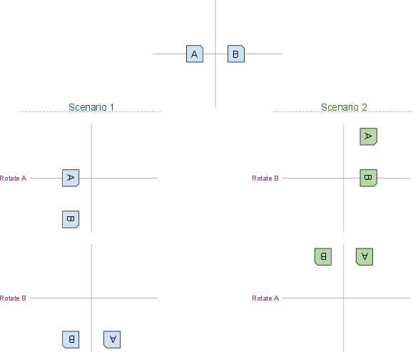
Below is a simple example:
We have two objects A(bluish) and B(reddish). They are animated as shown in the image below.


Questions:
Think of the following scenarios after switching at frame 3:
  1. If B, the current driver, moves at frame 3
    This means that A will move as well since B is the current driver
  2. If A, the previous driver, moves at frame 3
    In this case B does not move since A is not the current driver

As for the status of GroupConstraint, the basics work quite nice with the animation. The problem arises when the animation changes creating a pop. The constraint handles pop for certain cases, but not all. I have finished writing logic for detecting keyframe changes and checking if it affects the constraint output or not based on graph connections and also DAG hierarchy. I also have all the functions ready to update offset information at any switch keyframe. The last (hopefully last) part now is to make sure that the auto-pop correction works when changing the existing animation in different cases. For me, I have to look at few more scenarios since I am also working hard to make switching possible with only one keyframe instead of two consecutive keyframes. And the possibility of animating the followers independently while driven by the driver of the system also adds to the difficulty.

10 March, 2012

Group Constraint Update

It has been a great learning experience while building this constraint system. As I posted before, I have been working on a constraint that allows dynamic relationship between a group of transforms. Hence I have called this a "Group Constraint". I think this constraint will be very useful in building rigs where the driver in the group needs to be switched during animation. One such example could be a foot rig where multiple contact points are required. This constraint should allow bi-directionality(or multi-way directionality) so that between two or more transforms anyone can be the driver at any time during animation.

First step for me was to find out how to calculate the final output when switching driver transform in the group. I was suspecting that I would need some complex calculations, however after doing some research and learning a great deal about visualizing matrix multiplication I found that I just needed a simple calculation. Having a proper structure for attribute also helped in simplifying the calculations. First I used python to experiment and confirm that my logic would work the way I want and then I started building plugin using C++. I finished the basics first, building input-output attribtue structure, using setDependentsDirty to establish relationship and reading the attributes from DataBlock. When I tested this code I always got zero values in all the attributes in compute method. Later I found what the problem was and how to fix it (read about it Here).

Now I have got basic switching between drivers working. And during the switch all the offsets maintained. One of the advantages of the method that I am using is that all the followers are free to move while being controlled by the driver node. This allows for more freedom in animating. My main goal is to make this system such that there shall be no pop when switching between drivers, even when animation keys are updated. I am also looking for a way to avoid having to key driver attribute twice in consecutive frames to make a switch. Enum attribute type allows such stepped keys as default behavior, however the challenge is to calculate the output at this switch point. The way Group Constraint stores the offsets and how final output is calculated should allow for such feature, but I have to test it to see if it works in all cases.

The biggest challenge and what will actually be the backbone for many of the features is linked with detecting animation events. Exo Switch Constraint also utilizes callback functions to detect keying on the driver (master) node. However, I intend to use it for different purposes and it will allow me to correct any pop at the switching points when animation is updated. There are two options available in Maya to listen on animation update events:
  1. Listen for changes in all animation curves and in the callback check if animation change is related to the constraint node.
  2. Listen for only particular animation curves that are linked to input transforms of the constraint.
First option is actually simpler in a way that I don't have to keep track of animation nodes connected to constraint's inputs. However, it can affect the performance if a lot of attributes are being keyed which I do frequently while animating and I am sure many animators do too. So I have decided to take the second option. But it comes with a price of complexity. Second approach requires to detect when the animation nodes get connected to (or disconnected from) each individual element of  transform's translate, rotate and scale attributes. When connected we need to add callback for each animation node. And when animation is removed each of such callbacks should be removed for that constraint input. The callback function should know which input the call belongs to and process the event accordingly. Depending on number of inputs it can reach up to 30-40 callbacks. So I need to generalize the callback function. To do so I decided to pass some specific information(meta data) to this function in (void*) clientData pointer when callback is added. However, I need to allocate memory dynamically for such data so that it persists beyond its local scope. And this allocated memory needs to be freed when we remove the callback, otherwise we will get memory leakage. So it gets a little bit complicated to pass info through pointers during event calls and freeing the memory when we no longer need the callbacks. But when done it will be a flexible solution to manage multiple callbacks.

I haven't gotten around to create a demo of the first stage yet. But I would really like to share it some time soon to get some feedback. Let me know if you guys have any particular feature in mind for such constraint.

25 January, 2012

Notes: Building a multi-way (group) constraint

I have been highly inspired by the work that Andrea Maiolo and Tim Naylor did on multi-way constraint system, particularly what they presented at Siggraph 2006 on "Bi-Directional Constraining". I think I first saw their Siggraph work when I was at school in 2008 and that's what got me into understanding Maya's DG and matrix mathematics for 3D transformations. Since then I have tried to solve this kind of constraint system from time to time and I always got stuck as I didn't have enough knowledge at that time. Between 2008 and 2011 I have learned many things by challenging myself to new problems and also from inspirational work of talented technical artists. So I have picked up this project again and I think I have made some progress compared to my previous failed attempts. However, the progress it not hurdle free. Here are some notes on the issues I have encountered.

The challenges:
The first challenge we encounter when building a two-way constraint is the cyclic dependency. However, that's not really the main and only issue. It is possible to create connections and do calculations in such a way that we can avoid this cyclic dependency. The real challenge is that we can't really have true Bi-directional constraint (I say true for lack of a better word). When I started, my idea of a bi-directional constraint was that both nodes involved are the masters and both nodes affect each other at the same time without any switching. Based on this definition the main question is how to interpolate from one state to the other when both objects are moving each other. This leads us to another question, what should be the sequence of operations when calculating for the goal state? This is an important question and more so because the final state is the sum of transformations of both nodes. 

Sequence dependency:
One of the most important properties of rotational transformations is that the operations are non-commutative. We already know this based on what we know about rotation orders. Let's take an example. Let's say we have two transform nodes A and B in their initial state set apart by some distance with zero rotations on both. Let's assume that both A and B affect each other (bi-directionality). Now we apply 90 degree rotation in z-axis on both nodes. Now based on the sequence of operations we get different locations in the end result as illustrated below.


Solution?
Main problem here is that we are trying to treat both nodes A and B as masters at the same time. If we consider only one node as the master at a given point of time, we can avoid the problem of sequence dependency since only one node affects the others at a given time. ExoSwitch constraint uses a concept of driver nodes and driven nodes. Using this concept, we assign one driver for the constraint system at a given point of time to drive all the other nodes. So ExoSwitch constraint does not have a problem of finding the right sequence at a single point of time.

Alternatives?
I can't think of any simple way to record a sequence in which a user is manipulating the nodes involved in a multi-way constraint. However, I think it should be possible to implement a system where all the nodes are treated as masters (or drivers) at the same time. One idea would be to have some kind of iteration based solver that calculates the interpolation to reach the goal state when all the nodes are driving one another. Maya's FBIK comes to my mind, but it seems that it takes a bit different approach. This approach is to solve the system when user moves one of the nodes(effectors) and update all the nodes with their final coordinates. When you animate these coordinates on effectors, each node is interpolated independently. Even though it works for FBIK, this behavior is not quite desirable for a multi-way constraint system.

Still a long way to go for finishing a working multi-way constraint. I always get more hopeful when I solve a problem on the way. But I think I should look forward to the next problems on my path and be ready to challenge my small brain for some exercise :)

12 January, 2012

Mysterious "geometry" attribute and Geometry Constraint

Geometry constraint is a bit special because it does not connect its output to transform attributes of a constrained node allowing us to key them. Out of curiosity I looked at the connections in hyper graph and I see that output of the constraint node is connected to "geometry" attribute of the constrained node (any transform node). One would think that this attribute would have something to do with geometric data for display or deformation. However, the doc says "Geometry attribute used for positional constraints". Strange!

Here is an example of this connection used by geometry constraint:
locator1_geoConstraint.constraintGeometry -> locator1.geometry

We know following things about this "geometry" attribute based on the documentation:
  • It's a generic type attribute (it takes nurbsCurve, nurbsSurface, mesh etc. as input)
  • It affects translation attribute of a transform node (we can use it to control position)

Based on above information let's do some experiments and see what happens.
  • Create a nurbs sphere
  • Create a locator
  • Connect nurbsSphereShape1.worldSpace[0] -> locator1.geometry
And locator1sticks to the sphere! What happened here? My guess is that this particular attribute calculates/updates translation value based on given geometric data. Now, if you move the locator1 you will see another surprise, locator1 is constrained to the sphere! And this is working without a constraint! You can move the sphere around or change its shape and the locator1 will still be following it. So this is almost like a geometry constraint but without creating the constraint node. The only thing that would not work here is if you group the locator and move the group, i.e. if you move the parent of the locator. This is what is handled by geometry constraint and that's where attribute locator1.parentInverseMatrix comes into the picture. This attribute is used by the constraint to compensate for any transformation coming from parent hierarchy of locator1.

So this makes me think that "geometry" attribute was added when geometry constraint was added. Who knows!

05 January, 2012

MPoint '=' assignment operator and float[3]

All 3d packages define a 3D point as (x,y,z,w). Last property 'w' is included based on how homogeneous coordinate system works. And this 'w' always needs to be 1 when we do calculations. Maya's implementation of this 3D point is done in MPoint class. This class also defines '=' operator which will copy the values of a float[3] to the given point. But it's really not a good idea to do the following.

float myPt[3] = {1,1,1};
MPoint mayaPt = myPt;

The problem here is that Maya will assign values to x,y,z from myPt but not to 'w' leaving it 0. This is an invalid homogeneous coordinate as w=0 means the point is at infinity! So keep in mind that 'w' is important :)

04 January, 2012

Freedom of a constrained node

When you constrain a transform node using Maya's constraints, it stops inheriting transformations from its top hierarchy. However, if you just connect (for example) translation attributes directly or using simple arithmetic nodes, the connected node continues to inherit transformations from its parent. The difference is because of how a constraint calculates the final output. Let's do a simple experiment.
  1. Create a nurbsCircle and a locator.
  2. Group the locator (group1->locator1).
  3. Now point constrain locator1 by nurbsCircle1 (keep offset option off).

The locator1 should be stuck to nurbsCircle1. Notice that locator1 does not move if you move its parent (group1). Now zero them out, so everything is on the origin. Then move group1 2 units in y-direction. Check the position values of locator1, it changed to (0,-2,0)! So the constraint recalculates position of locator1 to keep it locked to nurbsCircle1. To do this, constraint node uses transformations of nurbsCircle1 and group1(parent of locator1). And the position of locator1 is calculated by converting world-space coordinates of nurbsCircle1 to local coordinates under group1 (parent of the constrained node). This calculation uses 'worldInverseMatrix' of group1 which is the same as 'parentInverseMatrix' of locator1. To get more idea about this have a look at this nice article by Hamish Mckenzie.

Now let's change this behavior. Disconnect this connection, locator1.parentInverseMatrix[0] -> locator1_pointConstraint1.constraintParentInverseMatrix and move group1, you should see that locator1 is moving with its parent now! Both group1 and nurbsCircle1 should affect position of locator1. What happened here is that by disconnecting parentInverseMatrix we stopped constraint node from compensating for movement of group1(parent of constrained node). Or the space in which final coordinates for locator1 needs to be calculated is fixed and not affected by locator1's parent.

That explains the reason behind why after constraining a node it stops inheriting transform values from its top hierarchy.

To make things interesting, let's try the following:
  1. Zero out all the transforms.
  2. Group "group1" (we get  group2->group1->locator1).
  3. connect "group2.worldInverseMatrix[0]" to "locator1_pointConstraint1.constraintParentInverseMatrix;"

What we did here is made point constraint consider group2 as the parent of locator1 instead of group1. So when constraint calculates position for locator1, it will compensate for group2, but not group1. This means that if you move group2, locator1 will not move but if you move group1 then locator1 will move!

Here is a diagram I put together that might be useful in understanding what I wrote. I have just repeated the same thing actually, but in different ways as I understood this.


20 December, 2011

Rigenerator: A Short Introduction

I am updating Rigenerator slowly, but steadily with exciting updates coming soon. Before I post any updates I thought it would be a good idea to post some introduction about this tool.

At a basic level Rigenerator is a tool to regenerate rigs in Maya. It allows you to gather information about selected rig by doing advanced traversal through Maya's scene graph. After gathering information and generating metadata the tool allows you to see what (dag & dg) nodes are part of your rig and then generate MA style code to reproduce the same rig in a single click. However, this is just the basic framework. We can build on top of this to add some really helpful and advanced features. The main features of Rigenerator are listed below.
  • Extract the part of the rig 
  • Rename and regenerate the rig using MA style code
  • Mirror the extracted rig
  • Abstract the rig code into a generalized module
At the core of the framework is a module for traversing maya scene graph with rule based conditions to extract a part of the rig. So you can select just the root nodes of your rig, for example left arm rig, and the rig analyzer will gather all the nodes involved in that rig. So if you have stretchy IK, the rig analyzer will find all the utility calculation nodes involved in the rig as well. There are lots of things to consider when analyzing a rig by traversing a scene graph. One major issue to tackle is to solve cyclic dependency if the nodes are connected in a circular way. Right now Rigenerator's graph analyzer is able to avoid it for the most part and solve it in the post analysis phase for simpler dependencies.

The next module is closer to MA exporter plugin, but with more functionalities. There are few things about maya Ascii code that are not helpful if you want to execute it directly in Maya. For example, -ci (cache internally) flag in addAttr will generate warning. And the major problem comes with all keyframe nodes as mentioned here. Apparently, MA file uses attribute ".ktv" to set key value pairs which cannot be used outside saved MA file because that attribute is configured to work only when reading MA file by Maya. So there are some challenges that can only be solved iteratively as they are discovered. To solve such problems and to support the fourth feature on the list, I have started writing a module that will parse MA commands and based on rules a set of MA commands will be replaced by regular mel commands. 

Mirroring a rig is another project. First I had to learn the logic behind mirroring transforms and orientation. Instead of using mel commands I decided to write functions to mirror transform values giving me the flexibility of playing with any numbers and not just maya nodes. For example, transformGeometry node stores frozen transform values in a matrix attribute ".txf". To decompose or mirror its value I need to feed this attribute to matrix class and use matrix methods. Mirroring logic is actually quite simple once you figure out the logic and math behind it. So I took some time to understand Transform matrix and vector math to be able to code them in python classes and then use them to mirror orientation. I will keep the details for another post. However, these are still very simple things compared to generalization of mirroring any rig. There are many challenges involved in generalized mirroring, some of which includes mirroring constraints based on how other objects are mirrored, using connection sequence to predict the mirroring of custom attributes etc. I believe that it's going to be very difficult to create a perfect solution that always mirrors the rig automatically as intended by the artist/rigger. However we should be able to provide a toolset and workflow to the users so they are able to specify inputs/settings and get the mirrored rig as they want.

Once I finish the brain tearing task of mirroring logic, I want to take Rigenerator further to convert MA style code into proper mel commands. For example if you create a constraint in the rig, MA code actually creates constraint by manually creating the node, setting all the attributes and connecting the constraint node to its input and output nodes. My goal is to convert all these MA commands into just a couple of lines of code by utilizing maya's built-in commands, e.g. pointConstraint, aimConstraint etc. Now that's actually very difficult as I have come to realize after thinking about the logic for a while (say around a year). The most difficult task is to come up with rules for each type of node and specifying logic for each node. The second part makes it very difficult to generalize the main logic. However, by iterative process if I am able to create a database of such rules and some toolset to make the rule/logic generation easier then it should be possible to accomplish this. What this means is that you actually don't have to write the code for your rig from scratch! You get a ready function with inputs to create your rig and you just need to optimize the code! I would love something like that and that's why I am very excited to build this functionality.

In summary, what I want to accomplish using Rigenerator is to allow riggers to focus more on inventing and experimenting in the rig creation process and not worry about reproducing it. Hopefully when the tool becomes stable enough I would like to release it for free and later make it open source when the code is a bit more cleaner (easily readable to others :) ). Stay tuned!

10 December, 2011

Some python goodies

I love coding in python and every time I work with it I feel enthusiastic about this programming language. While coding it is also exciting to learn new features and figure out what you can do with it. Following are some useful snippets that I am using in my rigging framework. 

1. Assign values from a list that is shorter or longer than the original list
I find this simple function handy since this allows me to assign values from a list that is shorter or longer than the target list. It acts like partial assignment, leaving elements intact in my original list if source list is shorter.
def assignValues(list1, list2):
    mapFunc = lambda a,b: a if b is None else b
    origLen = len(list1)
    list1[:] = map(mapFunc, list1, list2)[:origLen] 

tgtList = [1,2,3,4]
srcList = [0,0]
assignValues(tgtList, srcList)

2. Overriding [] (indexing) in python for 2d indexing We know that we can use __getitem__ to assign an array like behavior (or make object iterable). But how about making object behave like 2 or 3 dimensional array? You can actually pass tuple as a key to __getitem__  and then use unpacking feature of python. I found the following code online on activestate recipe website.
def __getitem__(self, (row, column)):
    return self._data[row][column]

3. Some great recipes on python website Some great code recipes and a very useful module.  http://docs.python.org/library/itertools.html#recipes
 

15 October, 2011

Eggroll setup update

I meant to post this for a while, but never got around to finish a demo of it. Inspired by Mike Best's eggroll setup, I wanted to do a similar setup because it was a good challenge. After my previously failed attempt I switched to a special matrix(found from google) to calculate rotation of the object around an axis using maya expression. This worked very well and I finally got the rolling working. However I still had some minor problem with small offset from the ground in some positions, it might be the pivot location that might be off. But more challenging is the sliding problem, though it's not very noticeable in the demo. I would like to come back to it later. Deformation of the egg should not be difficult to add to this setup as I am already counting in the bounding box volume in nodes calculation.

Later Mike was kind enough to share the script which gave me insight into his setup. Mine is not as good as his, but I was happy to get the egg rolling :)

This challenge sparked my interest in rigid body simulation. Hopefully in the future I will be able to take time into reading more about it (and begin to understand something!) to write my own little simulator. I am looking particularly for a real egg rolling simulation where the center of mass of rigid body is shifting based on the properties of the fluid (egg yolk and egg white).

Bare essential commands that create Maya's scene

If you open .MA maya file in notepad, you will see many lines of code based on your scene size. If you go through the code, no matter how big the scene is or how many nodes are there, the whole scene is created by only 4 commands! That's it! It's very easy to find this information, but what amazes me is that the programmers were able to abstract the logic of scene creation to the following atomic tasks:
  1. Creating nodes with parenting info
  2. Adding attributes
  3. Setting changed attributes
  4. Connecting the nodes
It is very easy to generate .MA style code by following the example of MA exporter plugin. I am using some parts of it in Rigenerator to save the part of the rig as code. My next goal is to be able to analyze this code and extract metadata information for each line. This will allow me to extract scene graph information by just looking at the code. So I am currently in process of designing the logic for a code parser module which will parse the code to extract node/attribute/connection information.